
Wind Turbine
This project represents my abilities in 2019

Completed Windmill Assembly
One of the most ambitious projects I have completed to date is that of the wind turbine that I designed and built. I wanted to create a wind turbine for some of the people that I know on an island I visit in Canada. In the winter months, power outages that last several days are frequent and often the residents need to use off road vehicles to leave the island. Due to the freezing temperatures, the batteries in these vehicles often discharge, and without power, the residents would have no means of leaving the island. Thus, the main goal for this windmill was the ability to power 12V car batteries.
I knew that I wanted to build a vertical axis wind turbine (VAWT) for its ease of mounting to the ground. Unlike a HAWT, a VAWT can simply be mounted the the ground using a single anchor buried several feet beneath the ground. Had I designed a HAWT, a concrete foundation would've been needed, which is difficult to source on the island. Before I began to design the full-scale version of the windmill, I wanted to test different blade designs on a smaller scale. In order to do this, I designed the blades in SolidWorks and 3D printed them. These prototypes were seated on skateboard bearings and had a mounting point for a small dynamo I could gather data from.


Vertical Blade Prototype


45° Blade Prototype
In my testing, the vertical blade design spun faster in the same amount of wind and thus resulted in a higher voltage out of the dynamo. With this knowledge, I set out to design the full size wind turbine.
In order to make the turbine as large and light as I can, I decided to construct the blades out of sheet metal. The sheet metal would provide a large surface area in the wind, as well as a rigid vertical frame. This design did provide a challenge in the fact that the sheet metal was aluminum, which I couldn't weld with my welder. Instead, I designed a series of 3D printed ribs that would be used to both hold the shape to the aluminum and connect the aluminum to the axle of the turbine. The ribs also housed the outer race of the automotive bearing on which the blades would rotate. Each blade's plastic rib was detachable from the other, enabling the blades to be removed from the axle for ease of transport.


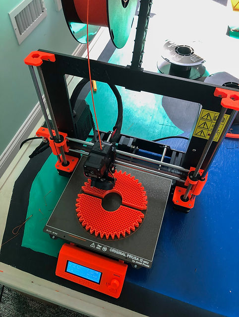
All the 3D printed parts on the turbine were printed by the printer I built myself, and all of the parts are made of PETG plastic, a more resilient, weather-proof alternative to the common PLA plastic.
Once the ribs were all printed, the next step was to insert the sheet metal into the slits of the plastic parts. The sheet metal I used was 20 gauge and thus was too rigid to bend without a roller, so I asked my local sheet metal store to roll it for me. Once I received the rolled aluminum, I was able to easily insert it into the plastic ribs. The aluminum was then drilled for anchor points to the plastic ribs. I also dulled and covered the edge of the metal to prevent it from cutting either myself or the end user.

The completed blades
With the blades of the turbine complete, I needed to construct an axle for the blades to rotate on. I sourced a 3/4 inch steel pipe from my local hardware store that would fit into the inner race of the bearing. Because there was a gap between the bearing and the pipe, I printed a washer to secure the bearing to the pipe while I welded it.

Once both of the inner races were welded to the pipe, I tested the blades spinning ability on the axle to determine if there was too much friction.

Welding the bearings to the shaft of the turbine
Spin Testing the Blades
With the blades and axle complete, there were two last things I needed to design and manufacture, the motor interfacing mechanism and the base.
When I was researching motor options for my windmill, I found a motor that could produce 12 Volts at around 600rpm. This is a high rpm generator, but it can produce current up to 100W, which can charge the battery at a reasonable rate. In order for my turbine to produce sufficient voltage, I calculated that I would need to use a gear ratio of 5 to 1 or greater.
.png)
Stock Motor
Printing the Gears
The motor needed to be securely held in place in relation to the blades for the gears to interface correctly, and I designed a three piece mount in SolidWorks to secure the motor to the axle.


I then attached the motor mount and gear to the axle and blades respectively to determine if they would interface properly.

The gears interfaced correctly, but the initial gear ratio of 2 to 1 was too low, so I increased it to 5 to 1.
With the gearing and motor mount complete, the final step was to create a base to keep the axle firmly vertical. In order to achieve this, I salvaged a steel wheel from an broken exercise machine we had to serve as the hub of the base. I decided to weld steel tubing to this hub as perpendicular legs, with extension legs sliding into these tubes to extend the legs when the turbine reached its testing destination.


Grinding the hub and the finished base structure
With the completed base structure, it was time for the first day of testing. With the help of a friend I set up the windmill in the back of my dad's truck at a local airport with a lot of wind.
Test Day 1
The first day of testing went amazingly, with the windmill proving itself capable of producing the 12+ Volts required to charge a car battery. The gears interfaced perfectly and the motor mount kept the generator securely on the axle. The only thing I could see that I wanted to correct the wobble that I was seeing when the windmill was rotating at full speed.
In order to minimize the amount of wobble in the axle of the turbine I designed two vertical posts that connect to the top of the axle. Each is comprised of 2 pieces of 1 inch square steel tube that I welded together. The posts are 90° apart from each other to limit the wobble in both the x and y direction relative to the z axis of the axle. The posts are attached to the legs of the base using 3D printed slots and connect to the top of the axle with a 3D printed hub.
Test Day 2

The improved, stabilized turbine

The hub for the stabilization posts
Stable rotation and gear interfacing
Voltage reading
Summary
As soon as I thought of the idea for this project, I knew it was the way I wanted to end my summer. I'm proud of the previous projects I've completed, but this specifically came together in a way that left me with no regrets about my design. The windmill can produce over 12 volts in a medium wind to charge car batteries, and is easily fixable. I plan on printing spare parts for all of the plastic components, and the only tool required to fix it is a M3 hex wrench. I'm going to package up the AC to DC converter in a waterproof container, and it will be ready for me to deploy for the residents of Miscou Island when I go up next summer.