
DIY CNC Mill
This project represents my abilities in 2020

Overview
After using my 3D printer for my projects last summer, I knew that I was rapidly approaching the limits of what I could make with an FDM machine. At the time, I wasn't sure what could enable me to take my projects to the next level, as I had previously considered CNC machining to be out of reach for a hobbyist, let alone a college student. On a whim, I decided to join a few machining forums on the internet to see what might be possible.
Surprisingly enough, there was a way for me to machine my own projects, a CNC mill conversion. A mill conversion seemed simple enough at the time, you purchase a cheap import manual mill and replace all the motion components with precision replacements, and attach stepper motors to drive the axes. Once I pulled the trigger and received all the components however, it quickly became apparent this was going to be no easy task.

The stock manual mill I purchased
I sourced the following components for my conversion:
-
1 Manual Mill
-
3 Precision Double Ball Nut Ballscrews
-
2 nema23 motors
-
1 nema34 motor
-
2 Motor mounts for nema23 motors on the x and y axes
-
1 motor mount for a nema34 motor on the z axis
-
3 couplers for the axes and motors
-
3 Stepper motor drivers
-
1 48V 12.5A power supply
-
1 5V 2A power supply
-
1 C10 Breakout board
-
A 32-bit Windows XP computer with a parallel port
-
Plenty of tooling/work holding fixtures
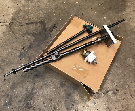
The original ACME screws

The new precision ballscrews

The first step of the conversion was to completely disassemble the manual mill. The only piece left was the base of the Y axis. After some research, I decided to pay a machine shop to mill out a larger cavity for the Y axis ballscrew, increasing the work volume of my mill. By replacing the origional ACME screw that was in the mill with a double ball nut ballscrew, I was going to lose ~1.5" of Y travel, so thats how much I asked them to mill out. I would've tried to do this step myself, but my new manual mill happened to be completely disassembled.
The next step of the conversion was to insert the Y axis ballscrew into the base. I ended up accidentally losing a few balls out of the screw in the process, so I unfortunately had to learn how to repack a ball screw.
The Base of the Y axis

Repacking the Y axis ballscrew

Inserting the ballscrew into the base and motor mount.
With the Y axis ballscrew in place, I then slid the x-axis baseplate onto the dovetail of the base. The Y motor mount was then attached to the base and the ball nut block was aligned to be perpendicular to the base and secured with a set screw to the x-axis base plate.

The Y-axis dovetail
Prior to being placed on the base plate, the x-axis base needed to have some material remove from its core to accomodate the x-axis ballscrew. This proved to be a common theme in this project, as the quality control process for these manual mills seems to be lacking on many dimensions.

The Y-axis Motor
I then inserted the gib and attached the motor to the y axis. The gib adjustment was key to the proper operation of the mill, and took several tries after troubleshooting issues with the movement of the axes.

Adding the x-axis ballscrew to the base
X-axis gib adjustment
I didn't realize it at the time, but the block on the Y-axis ballscrew that attached to the x-axis base actually interfered with the dovetail of the x-axis table when it was added. I noticed this when the gib for the x-axis would not insert close to its full length, while it had fit perfectly prior. It took a decent bit of trial and error to figure out the block was the issue.

Material removal to make room for the larger ballscrew

The x-axis table added to the mill
The x-axis table was added again, and the motor mounts and motor were secured to the table. The gib was adjusted to properly limit the travel of the table to be perpendicular to the other axes, while at the same time not creating too much friction between the ways.

Reattaching the spindle head to the mill

Attaching the z-axis motor mount and motor

My 3D printed mill head tramming tool
Once the head was on the mill, I had to tram it so that the spindle was completely perpendicular to the horizontal plane of the x-axis table. I ended up making my own tramming tool to save money, and I didn't get any back cutting with my largest cutter (2.5" face mill), so i think it did a decent job.
Electronics
While the electronics of this project may not be as much the focus of this project as the mechanical, I definitely learned just as much getting them up and running. This project represented the first time I'd used stepper motors and drivers, not to mention having to learn to copy operating systems from 20 years ago onto new hard drives.

The Completed Electronics Setup
Before I could determine if my stepper drivers were wired and setup correctly, I needed to solve the issue of the CAM computer. The whole theme of this project was cost efficiency, and many modern CAM programs cost hundreds of dollars a year to operate. But there is a workaround, MACH3. MACH3 is a piece of CNC control software origionally released in the early 2000s, that can be purchase for a one time cost of $175. The catch? It only runs on a 32-bit copy of windows XP, and requires a computer with a parallel port. This is quite a specific machine setup to find ~20 years after its release.

Using the linux CD to unlock the computer
Eventually I found an old machine on craigslist that fit the bill, and used some questionable software I found on the internet to bypass its password. Sadly however, its hard drive failed after a couple weeks. This set me back several weeks as I scrambled to find another machine, and I ended up having to buy a windows XP installation disc from across the world in order to load the OS onto new hard drives.

The electronics hardware
With the first working XP machine, I could then work to wire all of the electronics hardware together. This took a little trial and error, as a few of my components didn't have sufficient documentation or wiring diagrams.

The complete setup booting for the first time

The Final Electronics Box
Summary
While there were moments in the 6 months it took to get the mill fully functional that I had doubts about this project, it really did pay off in the end. Not only do I have a fully functional CNC mill in my garage for a fraction of the cost, but I also have the intimate knowledge of its hardware necessary to troubleshoot issues with machining jobs that may arise.
For videos of the mill in action, use the button below to check out the video of the mechanical watch I made!
This project really was a lot more than I had anticipated, and there's too many lessons and setbacks that I had to possibly include on this page. If you were interested and had any questions about the experience, feel free to give me a call at (978) 270-6115.
I can't discuss building the mill without thanking those who made it possible, namely my father, who helped me troubleshoot the build and graciously gave me the corner of his garage, and both my father and grandfather, who inspired in me a love of building early on in my life.